










 Why Higre
  Energy Storage
  Grid-Forming PCS
  Energy Management
  Solar Pumping System
  Higre Cloud
  For North America
  Selection & Guide
  System Design & Application
  Documents
  More
More 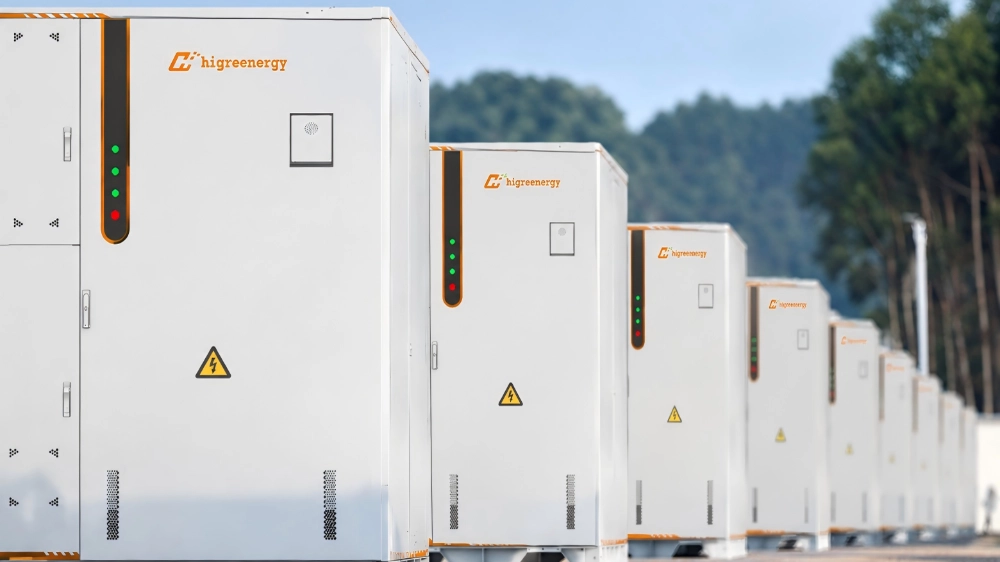
Energy landscape is undergoing a structural paradigm shift. Rapid load growth driven by data centers, advanced manufacturing, and electric mobility—coupled with tightening interconnection queues and severe weather events—has elevated Battery Energy Storage Systems (BESS) from discretionary peak-shaving assets to mission-critical infrastructure. However, maximizing revenue in complex ISO/RTO markets requires far more than procurement of generic battery capacity. It demands architectural precision.
For project developers, EPCs, and C&I energy directors, architectural selection is the single most decisive factor dictating CapEx efficiency, LCOS, safety compliance, and long-term project bankability under evolving tax frameworks.
1. BESS Architecture: The Anatomy of Modern Storage Systems
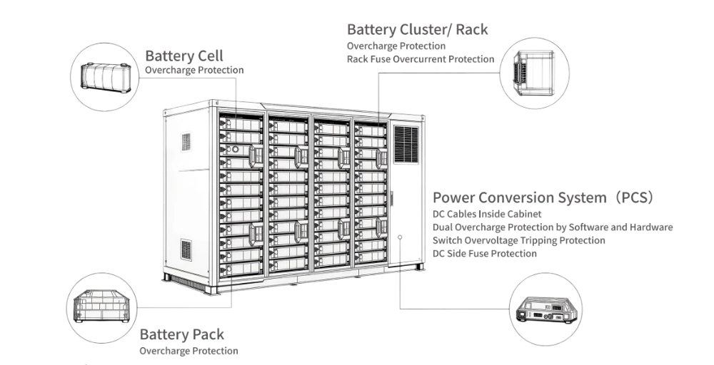
A utility-grade or commercial BESS is not merely a collection of battery cells; it is a complex, electro-chemically constrained power plant governed by multi-layer physics and digital controls. At an architectural level, modern BESS platforms synthesize five mission-critical subsystems:
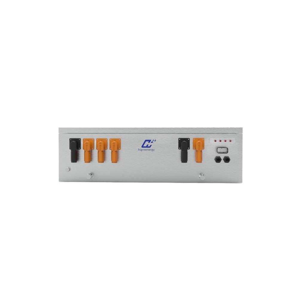
- Electrochemical Core (Battery Racks and Strings): Moving definitively past legacy 280 Ah formats, the 2026 industry benchmark centers on high-capacity 314 Ah LFP prismatic cells. Organized in high-voltage DC strings (standardized at 1500 VDC to minimize I2R resistive losses), these racks balance volumetric energy density with intrinsic chemical safety.
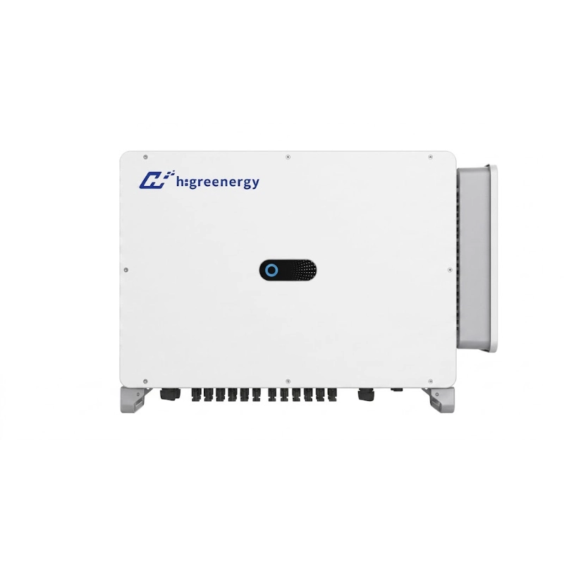
- PCS: Operating bi-directionally, the PCS converts DC energy to three-phase AC power. Modern utility designs incorporate four-quadrant, grid-forming inverter topologies equipped with VSG controls, enabling black-start capability and sub-cycle frequency droop control.
- BMS: Structured in a robust 3-tier hierarchy (Cell Monitoring Unit to Rack Controller to System Master BMS). The BMS executes real-time SoC, SoH, and SoP state estimation, dynamically adjusting charge limits to mitigate cell balancing drift and prevent thermal propagation.
- Thermal Management Architecture: High-density deployments demand active liquid cooling. Modern chillers utilize closed-loop, dielectric or inhibited glycol fluids routed across micro-channel cold plates beneath modules. This keeps intra-rack cell temperature differentials within 2 degrees Celsius, effectively eliminating localized hot spots and thermal derating.
- BOP and Safety: Multi-stage safety stacks engineered to satisfy UL 9540, UL 9540A, and NFPA 855 directives. These incorporate continuous off-gas detection (monitoring hydrogen, carbon monoxide, and VOCs at the ppm level), automated fire suppression, mechanical blast deflagration panels, and dedicated HVAC dehumidification.
2. AC-Coupled vs. DC-Coupled BESS
One of the earliest engineering crossroads in renewable integration is deciding between AC-coupled and DC-coupled architectures. Each topology brings distinct trade-offs in RTE, interconnection complexity, and economic monetization.
DC-Coupled Architecture
In a DC-coupled topology, both solar PV arrays and battery racks tie into a shared DC bus via bi-directional DC-DC converters before feeding into a central inverter.
- Elimination of PV Clipping:DC-coupled systems capture energy that exceeds the inverter AC capacity rating (clipping losses) and route it straight to the battery bank, elevating the Solar Resource Factor.
- Higher Charging Efficiency:Direct DC-to-DC charging bypasses double inversion (DC-AC-DC), securing an auxiliary efficiency gain of 2% to 4%.
- Single Interconnection Point:Streamlines interconnection applications with utilities, reducing switchgear footprints and medium-voltage transformer costs.
Disadvantages include higher engineering complexity, heightened vulnerability to single-point inverter failures, and challenging retrofit logistics on existing PV installations.
AC-Coupled Architecture
In an AC-coupled topology, the PV array and the BESS maintain independent inverters and tie together at the common AC busbar or facility switchgear.
- Operational Independence and Flexibility:Independent PCS units mean a failure on the PV side does not compromise storage availability. Storage can charge directly from the grid or the local array at will.
- Turnkey Retrofit Feasibility:Ideal for existing North American commercial rooftops or operational utility solar farms looking to add capacity without re-engineering string combiners or DC field infrastructure.
- Independent Dispatch:Enables simultaneous charging of the battery from off-peak grid energy while exporting 100% of solar generation to capture high real-time LMP (Locational Marginal Pricing) spikes.
Disadvantages include double inversion losses during solar charging cycles and slightly elevated BOS electrical hardware costs.
| Architectural Dimension | DC-Coupled Topology | AC-Coupled Topology |
| Round-Trip Efficiency (RTE) | Higher for solar charging (88% to 91%); avoids AC-DC conversion. | Standard (84% to 87%) due to intermediate AC conversion stage. |
| Interconnection and Permitting | Single utility interconnection filing; unified PCS footprint. | Dual or split capacity filings; highly standardized interconnection review. |
| Retrofit Adaptability | High friction; requires matching DC bus voltages and OEM protocols. | Seamless plug-and-play on existing AC distribution infrastructure. |
| Best-Fit Application | New-build greenfield Solar plus Storage projects targeting maximum ITC yield. | C&I demand management, microgrids, brownfield solar retrofits, standalone storage. |
3. C&I BESS Architecture
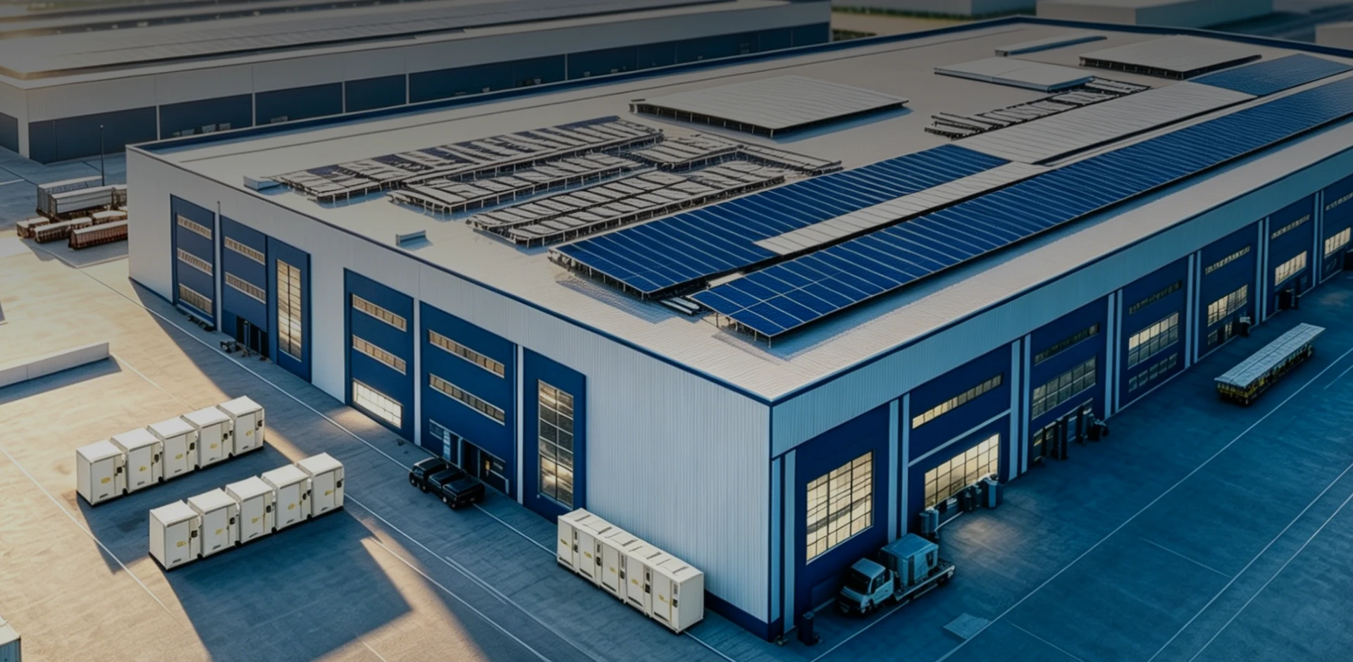
Commercial and Industrial applications (ranging from 100 kW / 200 kWh outdoor cabinets to multi-megawatt industrial microgrids) operate under intense economic scrutiny. Unlike front-of-the-meter assets that rely on capacity payments, C and I storage profitability hinges on high-speed localized responsiveness and behind-the-meter (BTM) optimization.
Key Architectural Pillars for North American C&I:
- Sub-Cycle EMS Control Loops: Industrial electricity bills in markets such as California (PG and E, SCE), the Northeast (ConEd, National Grid), and Ontario (IESO Global Adjustment) feature extreme demand charges tied to 15-minute peak intervals. The C and I BESS architecture must incorporate millisecond-level smart metering at the utility demarcation point, instantly dispatching power to shave sharp, motor-driven load spikes.
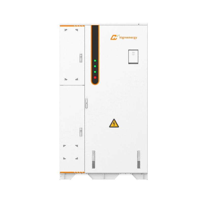
- Footprint-Optimized Outdoor All-in-One Cabinets: Industrial real estate is constrained. Modern C and I architecture emphasizes high energy density outdoor cabinets featuring IP55 and NEMA 3R exterior enclosures, integrated liquid cooling, and zero-clearance side-by-side spacing compliant with NFPA 855 separation mandates. Higre Energy C and I Battery Energy Storage Cabinet 261kWh represents this benchmark, delivering 261 kWh in a compact, factory-assembled footprint tailored for industrial yards and manufacturing facilities.
- Microgrid and Islanding Capability: To insulate data centers, food cold-storage, and chemical processing facilities from grid collapse, C and I systems increasingly integrate automated transfer switches (ATS) and grid-forming PCS units. This enables seamless, sub-16ms transition from grid-following to islanded microgrid operation during an outage.
4. Utility-Scale BESS Architecture
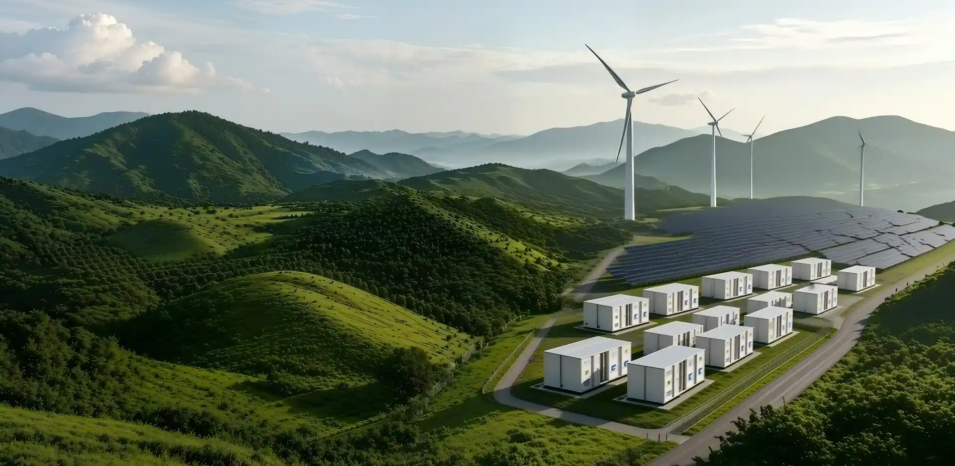
Utility-scale, front-of-the-meter storage installations (spanning 20 MWh to multi-gigawatt-hour complexes) are engineered to act as synthetic transmission assets and bulk grid stabilizers. The architectural imperative is centered on centralized efficiency, grid-forming robustness, and ultra-high volumetric energy density.
Key Architectural Pillars for North American Utility Scale:
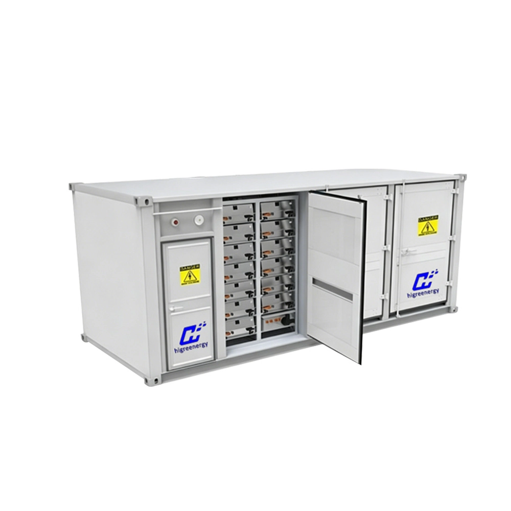
- High-Density Multi-Megawatt-Hour Containerized Blocks: Utility configurations deploy standardized 20-foot or 40-foot liquid-cooled ISO containers reaching capacities of 5 MWh to 10+ MWh per unit. Utilizing 1500 VDC architectures minimizes copper cabling costs and keeps auxiliary parasitic loads under 2.5% of gross capacity.
- Centralized vs. String PCS Topologies: Modern utility plants leverage clustered string PCS or centralized megawatt-scale inverters. String PCS topologies mitigate multi-string circulating currents and eliminate single-point-of-failure vulnerabilities, sustaining system availability above 98.5%.
- Advanced Grid-Forming Controls: As thermal coal and gas peakers retire across North America, grid operators (CAISO, ERCOT, NYISO) mandate that utility BESS provide synthetic inertia, primary frequency response (PFR), and black-start capabilities. Modern utility architectures implement advanced DSP controllers executing grid-forming algorithms to stabilize low-inertia networks.
5. The North American Regulatory and Financial Landscape
Executing an energy storage project in North America requires steering through intricate regulatory and financial frameworks. In 2026, technology architecture is directly coupled with legal eligibility and project bankability.
United States: Section 48E ITC, FEOC, and Safety Standards
- Section 48E Tech-Neutral Investment Tax Credit: Standalone BESS retains full eligibility for the 30% base Investment Tax Credit through 2033. Stackable bonus adders can propel total ITC monetization to 40%-50%:
- Domestic Content Bonus (+10%): Requires domestic U.S. steel and iron in enclosures and racks, alongside certified domestic manufactured product cost percentages.
- Energy Communities Bonus (+10%): Siting projects in designated brownfields or retired fossil-fuel plant regions.
- Foreign Entity of Concern and MACR Constraints: To qualify for tax credit underwriting, projects must certify that system supply chains meet the required Material Assistance Cost Ratio , restricting foreign control over critical battery minerals and active cell components. Architectural supply chains must feature transparent, vetted component traceabilities.
- Safety Compliance (NFPA 855 and UL 9540A): Fire safety codes prohibit large-scale BESS deployment without full UL 9540 certification and destructive UL 9540A test reports verifying zero flaming and thermal runaway containment within the enclosure.
Canada: Clean Energy ITCs and Regional Capacity Markets
- Federal Clean Economy Investment Tax Credits: Canada 30% Clean Technology ITC supports stationary BESS deployment, contingent on meeting prevailing wage and apprenticeship requirements.
- Ontario (IESO) Capacity Programs: The Long-Term RFP cycles in Ontario mandate high-availability assets delivering 4-to-8-hour continuous discharge to manage structural nuclear refurbishments and industrial electrification, favoring heavy-duty liquid-cooled architectures.
- Alberta (AESO) Market Reforms: Alberta restructured energy market incentivizes high-ramp fast-frequency response assets capable of withstanding extreme winter temperatures (-40 C) via specialized arctic thermal management packages.
Higre Energy Technology and Solutions: Engineering Bankable BESS Reliability
To bridge the gap between rigorous North American engineering standards and long-term project ROI, Higre Energy delivers an end-to-end portfolio of proprietary energy storage systems tailored for both Behind-the-Meter (BTM) commercial facilities and Front-of-the-Meter (FTM) utility infrastructures.
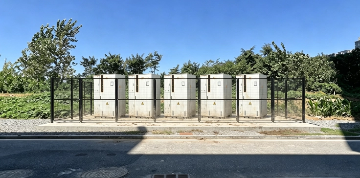
Flagship Architectural Solution: Higre Energy C & I Battery Energy Storage Cabinet 261kWh
Engineered explicitly for commercial campuses, manufacturing facilities, and microgrid installations, the Higre Energy C and I Battery Energy Storage Cabinet 261kWh integrates tier-1 314 Ah LFP cells, intelligent liquid cooling, multi-level fire protection, and smart power conversion into an ultra-dense, outdoor-rated enclosure.
- High-Energy-Density Architecture: Delivers 261 kWh of nameplate storage in an all-in-one footprint, drastically reducing site civil works and land requirements for footprint-sensitive industrial sites.
- Intelligent Liquid Thermal Management: Features micro-channel cooling plates directly coupled with battery modules, maintaining cell temperature variance within 2 degrees Celsius to prevent thermal derating and protect asset availability during continuous peak-shaving cycles.
- Factory Pre-Commissioned Plug-and-Play: Battery racks, liquid loop, PCS, and multi-gas detection are fully integrated and tested prior to shipping, saving up to 60% on expensive North American on-site field labor.
- Industrial-Grade Safety Matrix: Multi-tiered safety envelope engineered to comply with UL 9540 and NFPA 855, featuring combustible gas detection, early off-gas venting, aerosol and clean-agent fire extinguishing, and structural deflagration relief.
- Multi-Mode Operational Flexibility: Seamlessly coordinates peak shaving, dynamic demand charge mitigation, Time-of-Use (TOU) arbitrage, PV self-consumption, and backup islanding transitions.
Utility-Scale Portfolio: HGES Series Containerized BESS
For large-scale grid integration, utility renewable pairing, and synthetic transmission projects, Higre Energy deploys the HGES Series modular containerized platforms (10 MWh and 20 MWh scalable blocks), delivering grid-forming controls, 1500 VDC high-voltage efficiency, and 99%+ operational availability across the U.S. and Canadian power grids.
Why is the Higre Energy 261kWh Cabinet optimized for C and I demand charge management?
Industrial demand charges in North America are calculated on the highest 15-minute power peak during a billing cycle. Higre Energy 261kWh cabinet utilizes high-discharge-rate 314 Ah cells backed by liquid cooling, ensuring the system can output full nameplate power instantaneously without suffering thermal throttling or cell imbalance derating during unexpected facility load spikes.
How does architectural choice impact UL 9540 and NFPA 855 permitting in North America?
Fully factory-integrated cabinetized systems like the Higre Energy 261kWh system—with complete UL 9540 system listings and UL 9540A test verification—bypass the extensive, costly field evaluations required for site-assembled modular systems. Furthermore, proven thermal runaway containment enables local fire marshals (AHJs) to approve reduced unit-to-unit separation distances down to 3 feet under NFPA 855.
How do 2026 FEOC regulations influence BESS architectural procurement for U.S. projects?
Under 2026 FEOC mandates, systems seeking the full Section 48E ITC must satisfy the 55% non-FEOC Material Assistance Cost Ratio (MACR). System architectures must feature verified bills of materials, Tier-1 cell traceability, and domestic North American O and M and spare-parts pipelines to ensure compliance and prevent extended downtime during routine maintenance.